BLE Wearable System Architecture & Protocol Design
7 custom protocols to make a BLE wearable reliable in connectivity-unreliable care homes.
Custom Protocols Designed
Device · Gateway · Cloud
Alarm Delivery Guarantee
Tech Stack
The Problem
Standard Bluetooth was never built for life-safety alerts. If a resident presses their distress button while the connection is momentarily dropping, the alarm could simply disappear. The system needed custom communication rules that guaranteed every alarm would eventually reach a caregiver — no matter what happened to the network in between.
The Challenge
Off-the-shelf BLE profiles (GATT, HID, etc.) were not designed for the alarm-delivery guarantees required in a care-home safety context. A distress alarm triggered by a resident had to reach the caregiver app even if the BLE connection dropped mid-transmission, the gateway rebooted, or the device went out of range and reconnected minutes later. The system also needed to support OTA firmware updates over BLE without interrupting alarm monitoring, and allow the cloud to push configuration changes and messages to devices that may be offline for hours. Each of these scenarios required a custom protocol layer on top of raw BLE.
Architecture & System Design
Custom communication protocols bridge device, gateway hub, and cloud to guarantee alarm delivery even with network gaps. Counter-based handshake ensures no cloud messages are lost during disconnection. Firmware updates handled safely without interrupting alarm monitoring. Fail-safe system design handles power loss and corruption scenarios.
Seven protocols were designed to cover the full communication surface. The BLE Packet Definition specified the byte-level framing for all packet types (alarm, heartbeat, ILT scan, DFU trigger, sticky message) with version fields for forward compatibility. The Alarm State Protocol defined a state machine with states (Idle, Alarming, Acknowledged, Cancelled) and the exact transition triggers, retry timings (10 s resend until ack, 60 s reduced rate post-ack), and counter-matching rules to prevent replays. The Sticky Notification Protocol guaranteed delivery of cloud-to-device messages across connectivity gaps using a counter handshake: the device requests pending messages on heartbeat, the gateway responds with a counter, the device ACKs and requests the actual payload, repeating until counter reaches 255 (no pending). The OTA Protocol and DFU Trigger Sequence specified the dual-bank Nordic bootloader handoff, the 5-button DFU entry sequence, and the abort-to-alarm fallback. The RPC Protocol and WebSocket Protocol defined cloud-to-gateway and gateway-to-app communication respectively. The Fail-Safe Design document specified system behaviour under power loss, connectivity loss, and firmware corruption scenarios.
Code Walkthrough
3-step walk-through of the production implementation — file paths and intent shown above each block.
- 01
Step 1 of 3
Sticky message counter handshake
firmware/sticky_messages.cCare homes have frequent short BLE disconnections — a device moves out of gateway range for 30 seconds, reconnects, and any cloud-to-device config message sent during that window would be silently lost with a naive push model. The counter handshake flips the responsibility: on every heartbeat the device asks 'do you have anything for me?' The gateway responds with a counter; the device ACKs and repeats until the counter reaches 255 (nothing pending), guaranteeing delivery even after hours of disconnection.
cTakeawayPull beats push for unreliable links — the device drives the drain loop so the gateway never needs to know when a device is back online.
- 02
Step 2 of 3
Alarm state machine with counter-matched ACK
firmware/alarm_state.cA missed alarm in a care home is a patient safety event. The state machine's monotonic counter prevents a stale ACK from a previous alarm silencing a new one, and the 10-second retry loop keeps the alarm alive until an authorised caregiver explicitly acknowledges it — not just until the BLE connection drops and recovers.
cTakeawayCounter-matching the ACK costs 4 bytes and prevents the worst failure mode: a delayed ACK from a previous alarm silencing a live emergency.
- 03
Step 3 of 3
BLE chunk DFU — dual-bank flash write
firmware/dfu_transport.cNordic's dual-bank DFU keeps the running firmware in bank A while the new image is streamed chunk-by-chunk into bank B. If the BLE connection drops mid-update, the device stays on bank A — it never bricks. Only after a CRC-matched finalise call does the bootloader mark bank B valid and trigger the swap on next reset, leaving alarm monitoring uninterrupted throughout.
cTakeawayOffset-ACK on every chunk means a reconnect resumes where it left off; CRC validation before bank swap is the last line of defence against a corrupt image bricking a production device.
Results
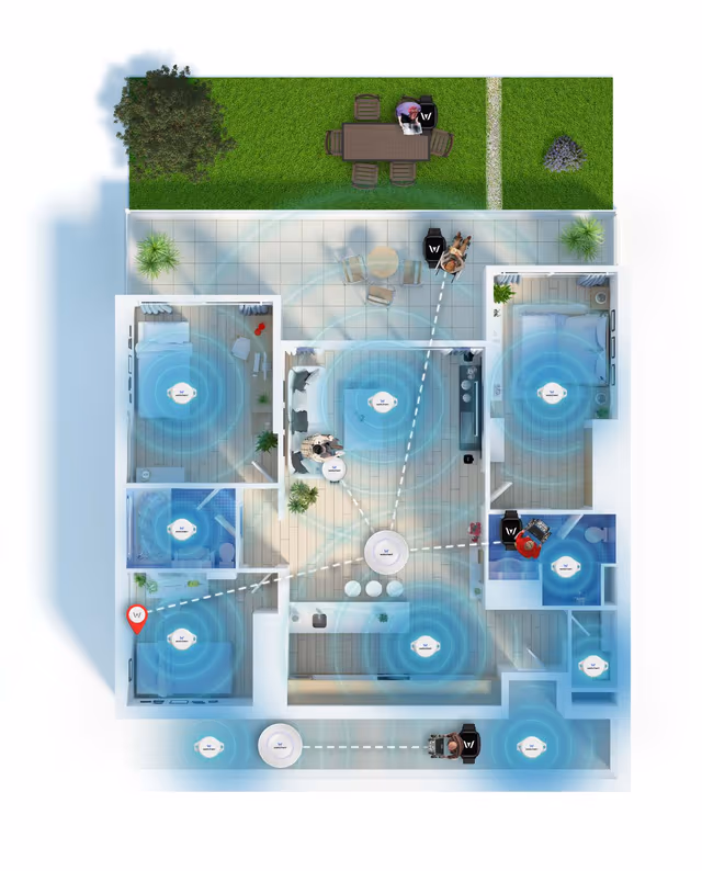
The sticky-message protocol proved critical in production: care-home BLE environments had frequent short disconnections (device moved out of gateway range, gateway rebooted for updates) and the counter-handshake mechanism ensured no cloud-to-device configuration messages or alarm acknowledgements were lost. The alarm state machine's retry logic sustained alarm visibility in the caregiver app across all connectivity gap scenarios observed in field deployments. The dual-bank DFU protocol allowed firmware updates to 40+ device revisions (v1.0.4 → v2.1.0) without a single device bricking in production. Watcherr subsequently rebranded as ixicare; the protocol designs and firmware architecture described here underpin the current ixicare platform.
Gallery & Demos
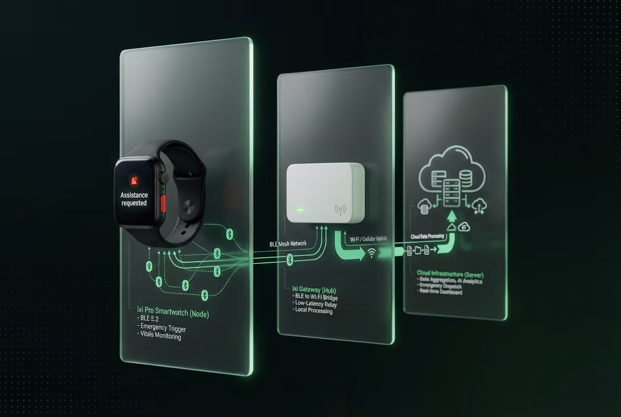
Gateway Hub Architecture
Central coordination point that bridges wearable devices and cloud services. Manages sticky message delivery, firmware updates, and real-time alarm propagation.
System Infrastructure Diagram
Multi-layer architecture showing device-gateway-cloud coordination with redundancy and fail-safe mechanisms for reliable alarm delivery.
Click any image or video to expand · ← → keys navigate
On-Device Activity Recognition — Care Wristband
End-to-end ML pipeline for on-device caregiver activity classification on a Nordic nRF52 wristband: raw IMU data collection and labelling, Edge Impulse model training across 23+ iterations, TFLite Micro firmware integration, and a real-time BLE activity viewer — all running in 64 KB RAM with no cloud round-trip.
Hardware & Firmware QA — IoT Wearable Platform
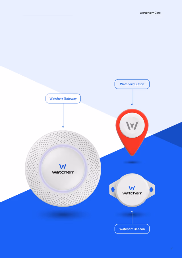
QA lead for the full Watcherr device family — owned test planning, structured firmware release gating, battery life validation, and risk assessment across Watcherr Lite (B7/B8), Watcherr Pro, and the G1 Gateway. 23 test reports spanning 10+ firmware versions, 344+ test cases passed with a 97.4% pass rate.
Product Management — Watcherr Safety Platform
Full product ownership across the Watcherr V1 lifecycle: authored the PRD and Product Specification, defined the V1 and V2 risk assessment matrices, owned the Q3 2024 product roadmap, and led the Watcherr Pro validation presentation. Bridged care-home operational requirements with hardware and firmware engineering constraints for a regulated IoT safety device.
Interested in this work?
Full architecture walkthrough and code review available during interviews.