Vision-Based Autonomous Quadrotor
Vision-guided autonomous flight and precision perching for agricultural monitoring.
Autonomous Perching
Control Mode
MS Thesis
Tech Stack
The Problem
Drones can monitor crops from above, but they can't see through a dense vineyard canopy — and GPS doesn't work reliably inside one. A drone that could land itself on a branch and observe from inside the canopy would be far more useful, but landing on a moving branch, using only a camera with no GPS signal, had never been done at this scale.
The Challenge
Commercial drones at the time required GPS for stable flight, making them unusable in dense vineyard canopies where satellite signal was occluded. The system needed to autonomously locate a branch-like structure, align itself, and perch using only camera input — with bird-leg mechanisms attached to the frame adding nonlinear mass distribution and making the dynamics significantly harder to stabilize.
Architecture & System Design
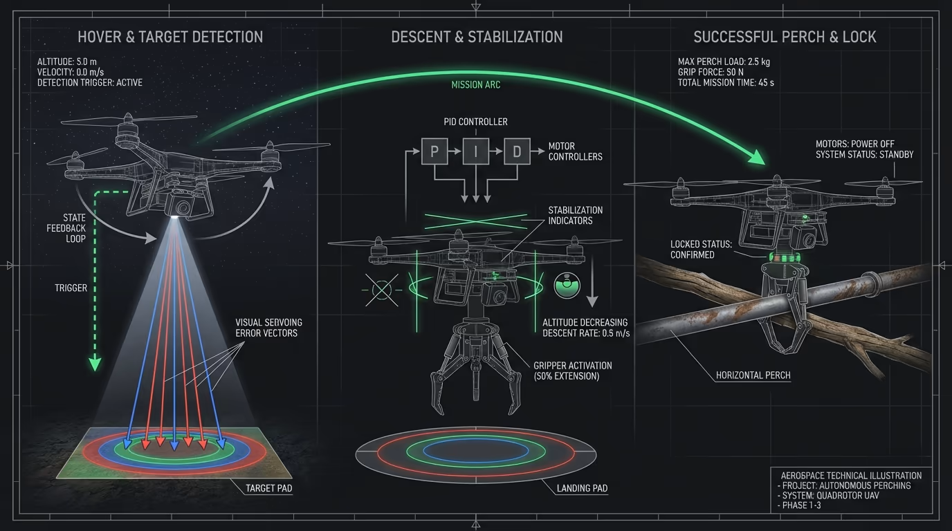
Camera-based visual control loop: drone sees target on ground, computes positioning error, adjusts flight path using feedback control. Perching mechanism attached to frame changes dynamics, requiring stability analysis and adaptive controller gains.
The quadrotor used a downward-facing camera feeding OpenCV-based feature detection to compute a visual error signal. A visual servoing loop drove the PID controllers for x/y positioning and yaw alignment. The nonlinear dynamics introduced by the bird-leg perching structures required a Lyapunov-based stability analysis and controller gain-scheduling. MATLAB/Simulink was used for initial simulation; the validated controllers were then ported to the onboard flight controller via ROS.
Code Walkthrough
3-step walk-through of the production implementation — file paths and intent shown above each block.
Results
Successfully demonstrated autonomous perching on simulated vineyard branch structures in lab conditions. The visual servoing controller achieved stable hover within 5 cm of the target using only camera feedback, with the nonlinear perching-leg dynamics compensated through gain scheduling. The work contributed to understanding of vision-only navigation in GPS-denied agricultural environments.
Gallery & Demos
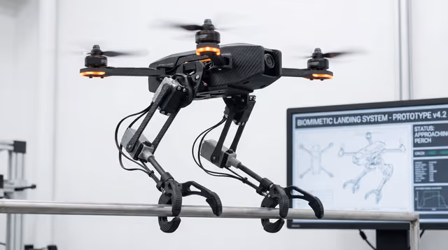
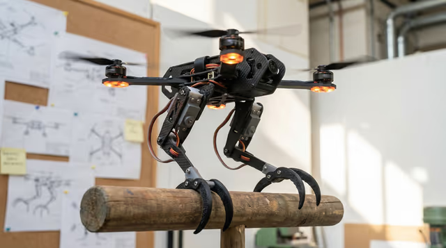
Lab Test Environment
Experimental setup showing the quadrotor approaching and perching on a rod-like target structure.
Flight Log Analysis
Time-series data showing position error and control actuation during autonomous approach and perching maneuver.
Click any image or video to expand · ← → keys navigate
More from University of Utah
Multi-Arm Coordination — 2-DOF QUANSER
Dual-arm robotic manipulation system using 2-DOF QUANSER robots with a master-slave architecture — one arm controlling position, the other controlling force — to collaboratively manipulate objects with precision.
Adaptive Backstepping — Indoor Micro-Quadrotor
Nonlinear controller design for an indoor micro-quadrotor with a suspended pendulum mass — a highly unstable configuration. Adaptive backstepping outperformed classical PID in robustness tests across multiple flight regimes.
Sensor-Based SLAM Navigation — iRobot Create
Autonomous mapping and navigation system on an iRobot Create platform using IR rangefinders and servo-mounted sensors for 360° SLAM — with RRT path planning to navigate complex maze environments.
PUMA 6-DOF Robot Arm — Forward & Inverse Kinematics
Full forward and inverse kinematics solver for a 6-DOF PUMA 762 robot arm, built from scratch using Denavit-Hartenberg parameters — with an interactive 3D MATLAB GUI featuring joint sliders, motion trail, and collision detection.
Sampling-Based & Graph-Search Motion Planning
MATLAB implementations of four canonical path-planning algorithms — Dijkstra, A*, PRM, and RRT — applied to a differential-drive robot navigating bitmap maps in configuration space, with real hardware execution on an iRobot Create.
Monocular Depth Estimation for UAV Perch Landing
C++/OpenCV vision system that estimates the 3D position and orientation of a landing perch from a single monocular camera — using image moments, covariance eigendecomposition for attitude, and focal-length triangulation for depth — enabling closed-loop visual servoing on a quadrotor.
RC Fixed-Wing Glider — Servo Actuation & Aerodynamics
Fixed-wing RC glider designed and built from scratch — two servos providing roll and pitch authority via aileron and flap control surfaces, with a brushless DC motor and ESC delivering forward thrust. Flight-tested outdoors.
Interested in this work?
Full architecture walkthrough and code review available during interviews.