Sampling-Based & Graph-Search Motion Planning
From graph search to random trees — four planners, one robot, real obstacle maps.
Implemented
iRobot Execution
Research Lab
Tech Stack
The Problem
A robot needs to find a safe path through a space filled with obstacles — without bumping into anything. But the straightforward approaches (search every possible position) get impossibly slow in larger spaces. The question was: which planning method is actually fast enough to work, and would it hold up on real hardware in a real room?
The Challenge
Planning collision-free paths for a differential-drive robot requires reasoning in configuration space (C-space), not just Euclidean space — the robot's orientation is a third degree of freedom, and circular robot geometry must be inflated into C-space obstacles. Grid-based methods (Dijkstra, A*) are complete but scale poorly; sampling-based methods (PRM, RRT) scale better but are probabilistically complete. The final assignment required deploying the best planner onto a physical iRobot Create navigating a real room mapped from camera images.
Architecture & System Design
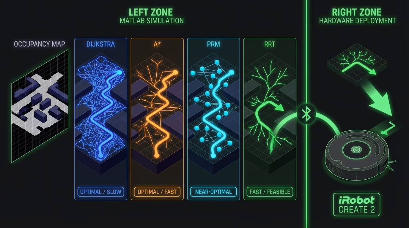
Path planning algorithms for robot navigation: Dijkstra and A* search graphs, PRM samples configuration space, RRT explores randomly. All tested on real robot with actual obstacle maps.
Dijkstra and A* operate on a weighted graph derived from a bitmap occupancy map — pixels become nodes, edges connect 8-connected neighbours, and A* uses Euclidean distance as the heuristic. PRM samples random free-space configurations, connects nearby nodes via a straight-line collision check, and queries the resulting roadmap with Dijkstra. The RRT implementation builds a tree by sampling random configs, finding the nearest tree vertex, propagating differential-drive kinematics (xDot, yDot, dirDot from left/right wheel velocities), and checking for map collision at each step. The final path is extracted via Dijkstra on the RRT adjacency matrix and executed on the iRobot Create via a MATLAB serial-port toolbox, with hardware playback scripts.
Code Walkthrough
3-step walk-through of the production implementation — file paths and intent shown above each block.
Results
All four planners successfully found collision-free paths in simulated bitmap environments. Dijkstra and A* produced optimal paths but were slow on large maps (>10s). RRT found paths in 2–5 seconds with up to 2000 tree vertices. The final assignment deployed RRT on the physical iRobot Create: the robot navigated a real room, executing the planned path via wheel velocity commands over Bluetooth serial. Path execution videos were recorded (LongPath.mp4, ShortPath.mp4).
Gallery & Demos
A* Algorithm Execution — Grid-Based Search
Dijkstra/A* graph search finding shortest path on occupancy grid with 8-connected neighbors.
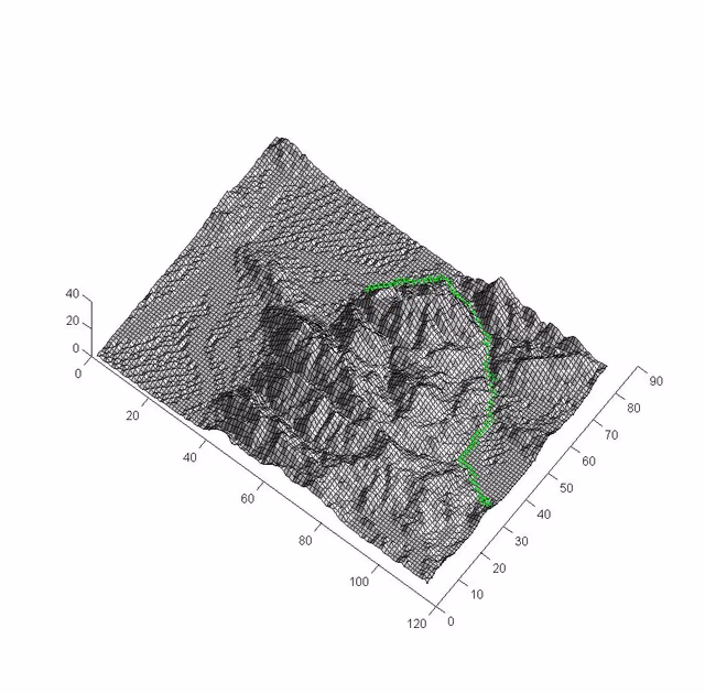
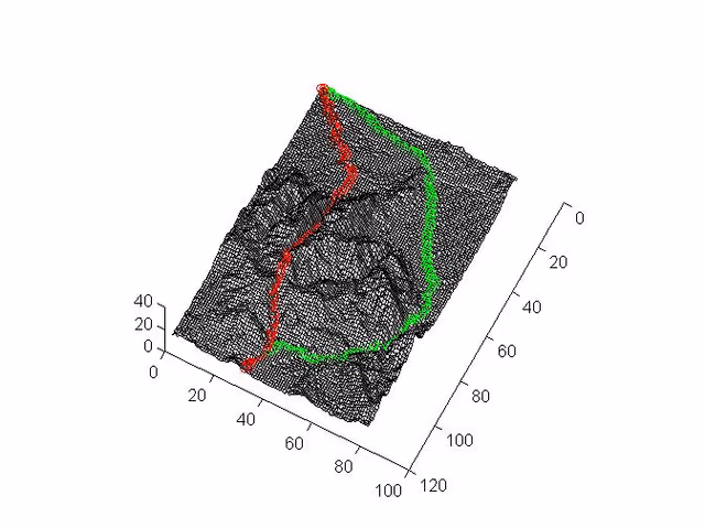
RRT Plan Visualization
Path found by the RRT planner on a 3D terrain cost surface, navigating from start to goal across the elevation landscape.
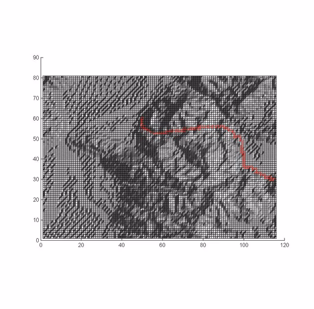
PRM Path Result
2D occupancy grid (top-down) showing the planned path extracted from the PRM roadmap, traversing the terrain from start to goal.
Click any image or video to expand · ← → keys navigate
More from University of Utah
Vision-Based Autonomous Quadrotor
MS thesis project: a quadrotor capable of autonomously taking off, navigating, and perching on branch-like structures using only visual feedback — designed for autonomous crop monitoring in agricultural fields.
Multi-Arm Coordination — 2-DOF QUANSER
Dual-arm robotic manipulation system using 2-DOF QUANSER robots with a master-slave architecture — one arm controlling position, the other controlling force — to collaboratively manipulate objects with precision.
Adaptive Backstepping — Indoor Micro-Quadrotor
Nonlinear controller design for an indoor micro-quadrotor with a suspended pendulum mass — a highly unstable configuration. Adaptive backstepping outperformed classical PID in robustness tests across multiple flight regimes.
Sensor-Based SLAM Navigation — iRobot Create
Autonomous mapping and navigation system on an iRobot Create platform using IR rangefinders and servo-mounted sensors for 360° SLAM — with RRT path planning to navigate complex maze environments.
PUMA 6-DOF Robot Arm — Forward & Inverse Kinematics
Full forward and inverse kinematics solver for a 6-DOF PUMA 762 robot arm, built from scratch using Denavit-Hartenberg parameters — with an interactive 3D MATLAB GUI featuring joint sliders, motion trail, and collision detection.
Monocular Depth Estimation for UAV Perch Landing
C++/OpenCV vision system that estimates the 3D position and orientation of a landing perch from a single monocular camera — using image moments, covariance eigendecomposition for attitude, and focal-length triangulation for depth — enabling closed-loop visual servoing on a quadrotor.
RC Fixed-Wing Glider — Servo Actuation & Aerodynamics
Fixed-wing RC glider designed and built from scratch — two servos providing roll and pitch authority via aileron and flap control surfaces, with a brushless DC motor and ESC delivering forward thrust. Flight-tested outdoors.
Interested in this work?
Full architecture walkthrough and code review available during interviews.