Sensor-Based SLAM Navigation — iRobot Create
From raw IR range data to a navigable map — full SLAM pipeline on embedded hardware.
Sensor Coverage
Path Planner
Research Lab
Tech Stack
The Problem
A robot dropped into an unknown room has no map. It can't plan a path to a destination it can't see, and it can't build a map it hasn't explored yet. The only way forward is to do both at once — map the environment while navigating it — using only the readings from its own sensors.
The Challenge
The iRobot Create platform has no built-in mapping capability. The challenge was to mount IR rangefinders on servo motors to achieve 360° coverage, build an occupancy grid map from the noisy sensor readings in real-time, and use that map to plan collision-free paths through a maze — all within the compute and power constraints of an embedded system.
Architecture & System Design
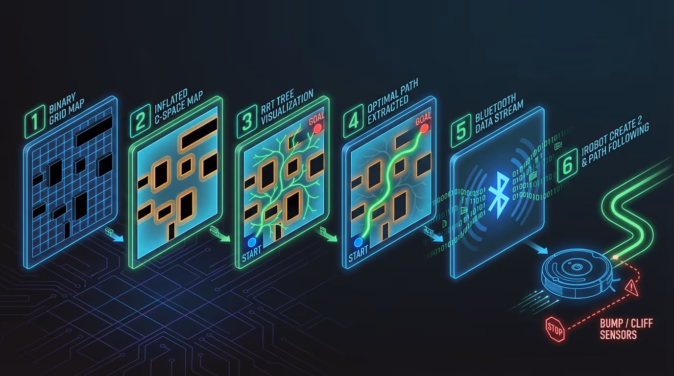
Rotating sensors build real-time 2D map of environment from range data. Occupancy grid algorithm marks free and occupied spaces. Path planning algorithm searches map for collision-free navigation routes. Robot executes waypoints using heading control feedback.
Two servo motors rotated IR rangefinder sensors to sweep the environment and collect range data at discrete angular increments. An occupancy grid algorithm converted range readings to a 2D binary map (occupied/free). The map was iteratively updated as the robot moved, with odometry used for dead-reckoning position estimates. A Rapidly-exploring Random Tree (RRT) planner searched the map for collision-free paths to the goal, with the robot executing waypoints via a proportional heading controller.
Code Walkthrough
3-step walk-through of the production implementation — file paths and intent shown above each block.
- 01
Step 1 of 3
IR range sweep → probabilistic occupancy grid
slam/occupancy.pyEach IR rangefinder reading gives range and angle relative to the robot. Bresenham's line algorithm traces the beam through the grid: every cell along the ray gets a small free-space credit, and the terminal cell gets a large occupied hit. Probabilistic updates (add/subtract, clamp 0–1) mean a single noisy reading doesn't immediately flip a cell — the map stabilises over repeated sweeps.
pythonTakeawayProbabilistic updates tolerate sensor noise — a single return doesn't hard-set a cell; the map stabilises after 3–4 overlapping sweeps, matching what was observed in practice.
- 02
Step 2 of 3
RRT path planner on the occupancy grid
slam/rrt.pyGrid-based search (Dijkstra/A*) is complete but slow on a 200×200 grid with a 3-DOF robot. RRT builds a random tree that biases growth toward unexplored free space, finding a path in milliseconds. A 5% goal-bias nudges the tree toward the target without the greediness that causes local minima in pure goal-directed search.
pythonTakeawayThe 5% goal bias is the key tuning parameter — too low and the tree explores randomly forever, too high and it gets stuck in local narrow passages between obstacles.
- 03
Step 3 of 3
Waypoint follower — iRobot Create serial execution
slam/execute_path.pyThe RRT output is a list of (x, y) waypoints in world coordinates. The robot executes them via a proportional heading controller: the bearing error between current heading and the next waypoint drives the turn radius, and odometry from wheel encoder deltas keeps the dead-reckoning position updated without GPS.
pythonTakeawayWrapping bearing error to [-π, π] before the proportional gain prevents the 2π discontinuity from commanding a full reverse spin when the robot overshoots 180°.
Results
The robot successfully mapped lab maze environments and navigated from start to goal positions autonomously. The occupancy grid converged to an accurate representation within 3-4 passes of the environment. RRT path planning consistently found collision-free paths in under 500ms on the embedded hardware.
Gallery & Demos
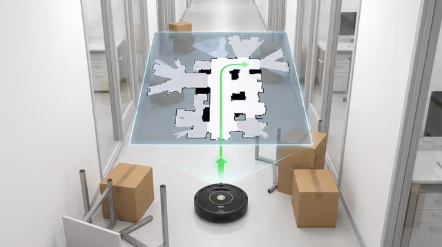
Occupancy Grid Map — SLAM Output
2D binary map built from 360° IR sensor sweeps showing occupied (walls) and free (navigable) spaces.
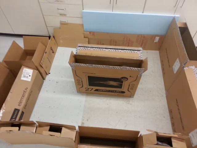
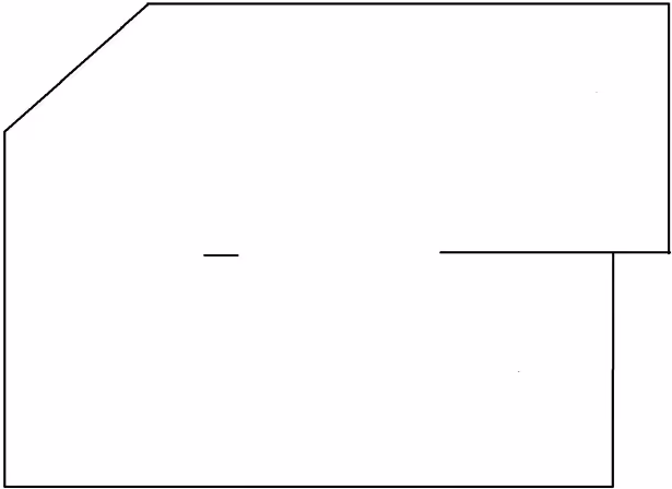
Lab Environment 1 — Test Space
First maze-like test environment where the robot performs autonomous mapping and navigation.
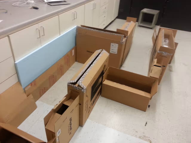
Lab Environment 2 — Alternate Configuration
Second test space with different wall layout to validate robustness of the SLAM pipeline.
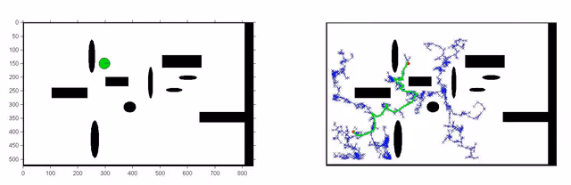
RRT Path Planning — Collision-Free Route
Rapidly-exploring Random Tree search result showing planned path from start to goal avoiding obstacles.
Planning Map — Cost Grid
Navigability cost grid used by the planner to guide the robot through open space while maintaining clearance from walls.
RRT Algorithm Demo — Tree Exploration
Real-time visualization of the Rapidly-exploring Random Tree building a collision-free path through the mapped environment.
Navigation — Short Path Execution
Robot following a brief planned path while continuously updating the occupancy grid from new sensor readings.
Navigation — Long Path Execution
Extended navigation sequence demonstrating sustained mapping accuracy and path tracking over multiple turns and obstacles.
Servo Motor Control — Sensor Rotation
Mechanism for rotating the IR rangefinder 360° to collect panoramic range data for real-time map updates.
Stepper Motor Initialization Test
Hardware testing of stepper motor control for servo mounting and sensor alignment verification.
Click any image or video to expand · ← → keys navigate
More from University of Utah
Vision-Based Autonomous Quadrotor
MS thesis project: a quadrotor capable of autonomously taking off, navigating, and perching on branch-like structures using only visual feedback — designed for autonomous crop monitoring in agricultural fields.
Multi-Arm Coordination — 2-DOF QUANSER
Dual-arm robotic manipulation system using 2-DOF QUANSER robots with a master-slave architecture — one arm controlling position, the other controlling force — to collaboratively manipulate objects with precision.
Adaptive Backstepping — Indoor Micro-Quadrotor
Nonlinear controller design for an indoor micro-quadrotor with a suspended pendulum mass — a highly unstable configuration. Adaptive backstepping outperformed classical PID in robustness tests across multiple flight regimes.
PUMA 6-DOF Robot Arm — Forward & Inverse Kinematics
Full forward and inverse kinematics solver for a 6-DOF PUMA 762 robot arm, built from scratch using Denavit-Hartenberg parameters — with an interactive 3D MATLAB GUI featuring joint sliders, motion trail, and collision detection.
Sampling-Based & Graph-Search Motion Planning
MATLAB implementations of four canonical path-planning algorithms — Dijkstra, A*, PRM, and RRT — applied to a differential-drive robot navigating bitmap maps in configuration space, with real hardware execution on an iRobot Create.
Monocular Depth Estimation for UAV Perch Landing
C++/OpenCV vision system that estimates the 3D position and orientation of a landing perch from a single monocular camera — using image moments, covariance eigendecomposition for attitude, and focal-length triangulation for depth — enabling closed-loop visual servoing on a quadrotor.
RC Fixed-Wing Glider — Servo Actuation & Aerodynamics
Fixed-wing RC glider designed and built from scratch — two servos providing roll and pitch authority via aileron and flap control surfaces, with a brushless DC motor and ESC delivering forward thrust. Flight-tested outdoors.
Interested in this work?
Full architecture walkthrough and code review available during interviews.