RC Fixed-Wing Glider — Servo Actuation & Aerodynamics
Hand-built fixed-wing glider: two servos, one BLDC motor, and enough aerodynamics to get airborne.
Control Surfaces
Thrust Motor
Outdoors
Tech Stack
The Problem
Building a glider that actually flies without an autopilot comes down to getting the physics right from the start. Put the weight too far back and it stalls; too far forward and it won't pitch up to take off. Make the control surfaces too large and the plane rolls uncontrollably; too small and you can't steer. With no electronics to compensate, the airframe itself has to be correct.
The Challenge
Designing a fixed-wing glider from first principles — sizing control surfaces, setting the center-of-gravity at 25–30% of the mean aerodynamic chord, and tuning servo throws to give enough roll and pitch authority without inducing flutter or coupling. The challenge was making a low-budget foam airframe flyable with minimal instrumentation and no autopilot.
Architecture & System Design
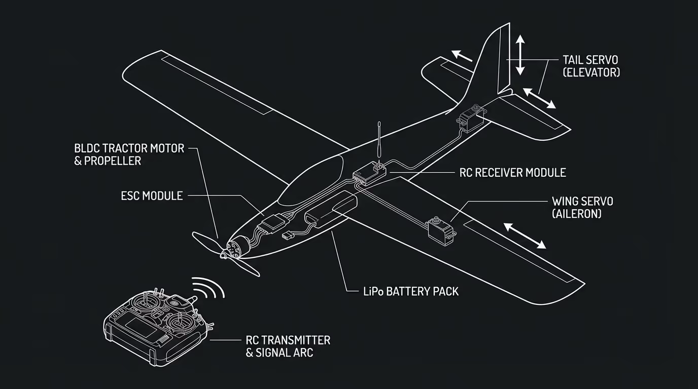
Fixed-wing aircraft with servo-controlled surfaces (ailerons, flaps) for pitch and roll. Brushless motor provides forward thrust. Integrated servo and motor control system for stable flight.
The airframe uses a conventional layout: a single wing with aileron servos for roll, an elevator/flap servo for pitch, and a nose-mounted brushless DC motor driving a propeller for thrust. The ESC translates PWM signals from the RC receiver (1000–2000 μs pulse width) into three-phase motor drive. Servo horns are connected to control surfaces via push-rods, with throw adjusted at the horn to set control sensitivity. CG was balanced by ballasting the nose and verified with a balance-point test before first flight.
Code Walkthrough
Non-proprietary extract demonstrating the core integration pattern.
Results
The glider achieved stable controlled flight on its first outdoor test. Roll authority from the ailerons was sufficient for banked turns without adverse yaw. The brushless motor provided adequate thrust for level flight and gentle climbs. Two documented flight sessions captured on video showed the aircraft completing multiple circuits before a controlled landing.
Gallery & Demos
First Flight — Takeoff and Banked Turn
Initial flight test showing stable takeoff, coordinated banking, and controlled descent. Demonstrates adequate aileron authority and pitch control.
Second Flight — Multiple Circuits
Follow-up flight showing sustained level flight, multiple banking turns, and smooth recovery to controlled landing. Validates aerodynamic stability and control system tuning.
Click any image or video to expand · ← → keys navigate
More from University of Utah
Vision-Based Autonomous Quadrotor
MS thesis project: a quadrotor capable of autonomously taking off, navigating, and perching on branch-like structures using only visual feedback — designed for autonomous crop monitoring in agricultural fields.
Multi-Arm Coordination — 2-DOF QUANSER
Dual-arm robotic manipulation system using 2-DOF QUANSER robots with a master-slave architecture — one arm controlling position, the other controlling force — to collaboratively manipulate objects with precision.
Adaptive Backstepping — Indoor Micro-Quadrotor
Nonlinear controller design for an indoor micro-quadrotor with a suspended pendulum mass — a highly unstable configuration. Adaptive backstepping outperformed classical PID in robustness tests across multiple flight regimes.
Sensor-Based SLAM Navigation — iRobot Create
Autonomous mapping and navigation system on an iRobot Create platform using IR rangefinders and servo-mounted sensors for 360° SLAM — with RRT path planning to navigate complex maze environments.
PUMA 6-DOF Robot Arm — Forward & Inverse Kinematics
Full forward and inverse kinematics solver for a 6-DOF PUMA 762 robot arm, built from scratch using Denavit-Hartenberg parameters — with an interactive 3D MATLAB GUI featuring joint sliders, motion trail, and collision detection.
Sampling-Based & Graph-Search Motion Planning
MATLAB implementations of four canonical path-planning algorithms — Dijkstra, A*, PRM, and RRT — applied to a differential-drive robot navigating bitmap maps in configuration space, with real hardware execution on an iRobot Create.
Monocular Depth Estimation for UAV Perch Landing
C++/OpenCV vision system that estimates the 3D position and orientation of a landing perch from a single monocular camera — using image moments, covariance eigendecomposition for attitude, and focal-length triangulation for depth — enabling closed-loop visual servoing on a quadrotor.
Interested in this work?
Full architecture walkthrough and code review available during interviews.